• Home
  • Archive by category "Learning"

Checklist to Perform Central Chilled Water Pant Inspection

  1. Purpose
    The subcontractor shall perform a complete inspection, testing, and condition
    assessment of the Central Chilled Water Plant
    (CWP) to evaluate the operational
    condition of eight (10) water cooled Chillers, each having capacity of 1100 TR and
    identify the extent of overhaul, repair, replacement, and maintenance activities
    required to restore the plant to reliable and efficient operation.
  1. Scope of Services
    The subcontractor shall provide all necessary manpower, supervision, tools,
    instruments, testing equipment, consumables, transportation, and documentation
    required to execute the inspection.
    2.1 Plant Survey and Data Collection
  • Conduct site visit and detailed survey of the entire chilled water plant.
  • Review available O&M manuals, maintenance records, equipment
    datasheets, and historical operating data.
  • Verify equipment inventory and nameplate data.
  • Record operating parameters and current equipment condition.
    2.2 Chillers Inspection
    Inspect all installed chillers including but not limited to:
  • Compressor condition assessment.
  • Refrigerant circuit inspection.
  • Oil analysis and lubrication system inspection.
  • Motor insulation resistance testing.
  • Vibration measurements.
  • Bearing condition assessment.
  • Evaporator and condenser condition evaluation.
  • Tube fouling assessment.
  • Control panel and safety devices inspection.
  • Refrigerant leak inspection.
  • Review of operating logs and alarm history.
    2.3 Pump & Piping Inspection Requirements
  • Contractor shall inspect the existing nine (9) primary chilled water pump, each
    having capacity of 1900 gpm, motor size 100 hp (approx.)
  • Contractor shall inspect the existing eight (8) condenser water pump, each
    having capacity of 3300 gpm, motor size 100 hp (approx.)
  • Contractor shall inspect all the existing chiller plant piping for any corrosion.
    Chiller plant piping consists of 14” dia, length 250 m (approx.), 10” dia, length
    250 m (approx.).
    2.4 Instrumentation and Control System
  • Functionality test for all Packaged instruments.
  • Functionality test for Control Valves.
  • Instrument cables integrity test.
    2.5 Building integrity assessment
  • Structural integrity assessment of the steel structure for single story steel
    building (size 50 m x 50 m approx.) with concrete foundation.
  • Structural integrity assessment of five (5) concrete foundations.
  1. Testing Requirements
    The subcontractor shall perform, where applicable:
  • Vibration analysis.
  • Thermographic inspection.
  • Ultrasonic testing.
  • Motor insulation resistance testing.
  • Chiller Oil analysis.
  • Water quality testing.
  • Operational performance testing.
  • Flow and pressure measurements.
  • Functional testing of controls and safety devices.
  1. Deliverables
    The subcontractor shall submit the following:
    4.1 Inspection Report
    A detailed report including:
  • Executive summary.
  • Equipment inventory list.
  • Condition assessment for each equipment item.
  • Identified defects and deficiencies.
  • Test results and measurements.
  • Photographic records.
  • Risk assessment of identified issues.
    4.2 Overhaul Recommendation Report
    The report shall include:
  • Recommended overhaul scope for each equipment item.
  • Required repairs and replacements.
  • Spare parts requirements.
  • Manpower estimate.
  • Recommended shutdown duration.
  • Priority classification (Critical, Major, Minor).
  • Remaining useful life assessment.
  • Budgetary cost estimate for overhaul activities.
    4.3 Final Assessment Matrix
    The subcontractor shall provide a condition index and recommendation matrix
    identifying:
  • Equipment requiring complete overhaul.
  • Equipment requiring partial overhaul.
  • Equipment requiring replacement.
  • Equipment suitable for continued operation.
  1. HSE Requirements
  • Comply with all Client and site HSE requirements.
  • Obtain necessary work permits before commencement.
  • Follow lockout/tagout (LOTO) procedures where applicable.
  • Ensure personnel are adequately trained and certified.
  1. Exclusions
  • Actual overhaul, repair, replacement, or procurement activities.
  • Major dismantling unless specifically authorized.
  • Refrigerant recovery and recharging unless requested separately.
  1. Completion
    The subcontractor shall complete the inspection and submit the final condition
    assessment and overhaul recommendation report within the period specified in
    the contract.
    Outcome: The final deliverable shall provide a comprehensive basis for defining
    the complete overhauling scope, budget estimate, execution strategy, and
    shutdown plan for the Central Chilled Water Plant.

Want to learn more about Chilled Water Testing, Chiller Oil Testing, Grease Testing etc? you may visit our dedicated page LAB TESTING

Should you have any enquiries and looking for a competitive quote, feel free to contact us 24/7:

get a quote

Get a Quote Today
Instant response!
[email protected]
Middle East – Far East – Africa – Europe – America – Australia – Asia

contact today

Hydrocarbon Fraction Splitting Characterization C6+, C7+, C14+, C36+

Expert Technical Training Note: Hydrocarbon Fraction Splitting & Extended Characterization (C6+, C7+, C14+, C36+)

Natural Gas Testing

Core Objectives

This technical module establishes operational standards for characterizing heavy hydrocarbon fractions (C6+ through C36+) in natural gas testing. Laboratory technicians, measurement engineers, and production chemists will learn to:

  1. Select appropriate analytical standards (GPA 2261, GPA 2286, GPA 2186, ASTM D1945).
  1. Execute proper backflushing and capillary column separation techniques.
  1. Calculate physical properties (gross heating value, relative density, compressibility factor, and Hydrocarbon Dew Point) without introducing operational bias or calculation errors.

1. Analytical Method Hierarchy & Standards Overview

Standard natural gas compositions group heavy fractions into lumped pseudo-components (e.g., C6+). Advanced thermodynamic modeling, pipeline custody transfer, and custody dew point management require extended analysis (C7+, C14+, C36+).

┌─────────────────────────────────────────────────────────┐

│                     Standard Gas (GPA 2261)            │

│                     Lumped C6+ Peak                     │

└────────────────────────────┬────────────────────────────┘

                             │ Extended Analysis

                             ▼

┌─────────────────────────────────────────────────────────┐

│                 Extended Natural Gas (GPA 2286)          │

│               Individual C6 to C14+ Separation          │

└────────────────────────────┬────────────────────────────┘

                             │ Deep Characterization

                             ▼

┌─────────────────────────────────────────────────────────┐

│              Heavy Gas Condensate / Rich Gas            │

│              Simulated Distillation to C36+             │

└─────────────────────────────────────────────────────────┘

Method / StandardTarget FractionSeparation TechniquePrimary Application
GPA 2261 / ASTM D1945C6+ (Lumped)Packed/Capillary Column with Backflush to TCDPipeline custody transfer, standard tariff compliance.
GPA 2286C7+ / C14+ (Split)Dual Column (Packed + Capillary) with TCD & FIDDeep gas processing plants, liquid recovery (NGL) optimization.
GPA 2186C14+ / Liquid NGLTemperature-Programmed GC / FIDDemethanized liquids, rich gas condensates.
High-Temp SimDis / Extended GCC36+High-Temperature Capillary GC / FIDEquation of State (EOS) tuning, Black Oil & Condensate PVT modeling.

2. Chromatographic Mechanics & Hardware Configuration

Standard C6+ Backflush Technique

  • Mechanism: Hydrocarbons heavier than Isopentane (n-C5) are retained on a short precut column while light gases (N2, CH4, CO2, C2-C5) pass to the analytical column.
  • Valve Timing: At a pre-calculated retention time, the switching valve reverses flow across the precut column, backflushing all C6 and heavier molecules as a single consolidated peak into the Thermal Conductivity Detector (TCD).
  • Assumed Ratio for Property Calculation: Unless characterized, the default C6+ pseudo-component is mathematically split as:
  • 60\%\text  C6\text (Hexane)
  • 30\%\text  C7\text (Heptane)
  • 10\%\text  C8\text (Octane)

Extended C7+, C14+, and C36+ Separation

  • Hardware: Utilizes a standard Gas Sampling Valve (GSV) coupled with a capillary column (e.g., 100\text m \times 0.25\text mm Dimethylpolysiloxane DB-1 or HP-1) and a Flame Ionization Detector (FID).
  • Thermal Ramp: Temperature programming starts at low temperatures (-10^\circ\textC to 40^\circ\textC) to focus volatile fractions, then ramps at 5^\circ\textC to 15^\circ\textC/min up to 320^\circ\textC+ to elute heavy alkanes, cycloalkanes, and aromatics.
  • C36+ High-Temperature GC: Requires high-temperature polyimide-coated or metal capillary columns operating up to 400^\circ\textC with cool on-column injection to avoid thermal degradation of heavy waxes.

3. Sampling Protocols & Contamination Control

Sampling errors disproportionately affect C6+ through C36+ fractions due to phase behavior changes inside sampling vessels.

                  ┌───────────────────────────────┐

                  │      Heated Probe in Main     │

                  │        Gas Stream Line        │

                  └──────────────┬────────────────┘

                                 │

                                 ▼

                  ┌───────────────────────────────┐

                  │     Heated Regulator System   │

                  │   (Maintain T > Dewpoint +20°F)

                  └──────────────┬────────────────┘

                                 │

                                 ▼

                  ┌───────────────────────────────┐

                  │    Heated Transport Tubing    │

                  │       (Trace Heating)         │

                  └──────────────┬────────────────┘

                                 │

                                 ▼

                  ┌───────────────────────────────┐

                  │ Constant Pressure Cylinder /  │

                  │      Chromatograph Loop       │

                  └───────────────────────────────┘

Key Rules for High-Fraction Sampling

  1. Maintain Thermal Envelope: Sampling lines and regulators must be heated to at least 15^\circ\textC (30^\circ\textF) above the predicted Hydrocarbon Dew Point (HDP). Drops in line temperature cause retrograde condensation, stripping C14+ and C36+ components from the vapor phase.
  1. Phase Isolation: Ensure liquid entrainment is avoided unless using specialized liquid injection valves for NGL/condensate testing.
  1. Materials: Use sulfinert/silcosteel-treated stainless steel tubing to prevent adsorption of aromatic heavier compounds (C6-C9 aromatics) or trace sulfur compounds.

4. Technical Calculations & Property Assignment

To calculate the Gross Heating Value (BTU/SCF), Specific Gravity, and Compressibility (Z) from an extended GC run, heavy pseudo-components must be properly characterized.

Characterization Steps

  1. Group Quantification: Sum the total area under peakseluting within specified retention windows:
  1. C6 Window: n-C5 elution end to n-C6 elution end.
  1. C7+ Fraction: Sum of all peaks eluting after n-C6.
  1. C14+ Fraction: Sum of all peaks eluting after n-C13.
  1. C36+ Fraction: Residual material eluting after n-C35.
  1. Molecular Weight & Density Matching: Assign physical constants to the split fractions using GPA Standard 2145 physical property tables.

\textMWCn+ = \sumi=n^N xi \cdot \textMWi

\textDensityCn+ = \frac\sum xi \cdot \textMWi\sum \left( \fracxi \cdot \textMWi\rhoi \right)

  1. Hydrocarbon Dew Point Impact:
  1. A single part-per-million (ppm) shift in C14+ content can shift the Hydrocarbon Dew Point by 5^\circ\textC to 15^\circ\textC.
  1. Using an uncharacterized C6+ assumption in rich gas thermodynamics leads to severe underestimation of liquid drop-out risks in downstream compressors.

5. Troubleshooting & QA/QC Checklist

PhenomenonPotential Root CauseCorrective Action
Incomplete C6+ Backflush PeakPrecut column valve timing drifted; carrier gas flow rate shifted.Recalibrate backflush switch time using a standard calibration gas containing n-C5, n-C6, and n-C7.
Baseline Drift on C14+ / C36+ RampsStationary phase column bleed at elevated temperatures (>300^\circ\textC).Execute baseline subtraction run (blank run); condition column or lower max temperature limit.
Peak Tailing on Heavy AlkanesCold spots in gas injection port, sample line, or transfer line.Inspect heated zones. Ensure transfer line temperature is maintained uniformly without cold junctions.
Low C14+ Recovery vs. Field HistoryRetrograde condensation inside sampling cylinder during transport.Heat sample cylinder to 60^\circ\textC (140^\circ\textF) for at least 2 hours prior to injection into the GC loop.

Want to learn more about Gas tests? you may visit our dedicated page Gas Testing

Should you have any enquiries and looking for a competitive quote, feel free to contact us 24/7:

get a quote

Get a Quote Today
Instant response!
[email protected]
Middle East – Far East – Africa – Europe – America – Australia – Asia

contact today

Groundwater Standard Testing Guide

How to Analyze Groundwater

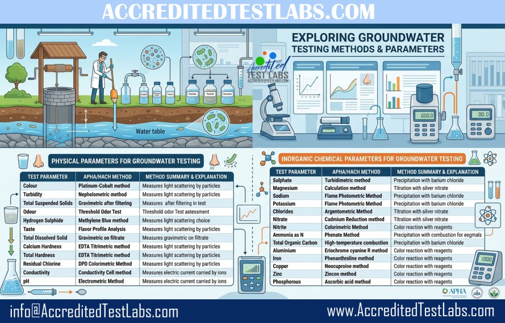
Groundwater testing evaluates physical appearance, organoleptic properties, mineral content, and inorganic chemical composition. Testing adheres to standardized methodologies established by the American Public Health Association (APHA) and HACH protocols to ensure analytical precision and regulatory compliance.

groundwater testing guide

Physical Parameters

Physical parameters measure the aesthetic, sensory, and fundamental physical properties of groundwater.

  • Colour (APHA 2120 B): Evaluates organic decay or mineral presence via visual comparison against platinum-cobalt standard solutions.
  • Turbidity (APHA 2130 B): Measures water clarity by quantifying light scattering caused by suspended particles using a nephelometer.
  • Total Suspended Solids / TSS (APHA 2540 D): Determines the mass of insoluble matter retained on a filter disc after oven-drying at $103\text{–}105^\circ\text{C}$.
  • Odour (APHA 2150 B): Detects volatile compounds through human sensory panels using the Threshold Odor Test (TOT).
  • Hydrogen Sulphide (APHA 4500-S²⁻ D): Measures dissolved rotten-egg odor gas using methylene blue colorimetry.
  • Taste (APHA 2160): Evaluates flavor characteristics via a Flavor Profile Analysis (FPA) panel.
  • Total Dissolved Solids / TDS (APHA 2540 C): Measures dissolved minerals, salts, and metals left after evaporating a filtered sample at $180^\circ\text{C}$.
  • Calcium Hardness (APHA 2340 B & C): Quantifies dissolved calcium ions via EDTA titration using a specific indicator.
  • Total Hardness (APHA 2340 C): Measures combined calcium and magnesium ions via EDTA titration using Eriochrome Black T indicator.
  • Residual Chlorine (APHA 4500-Cl G): Quantifies free or combined disinfectant levels using DPD colorimetry.
  • Conductivity (APHA 2510 B): Measures the electrical current carried by dissolved ions using a conductivity cell and meter.
  • pH (APHA 4500-H⁺ B): Measures active hydrogen ion concentration using an electrometric glass electrode meter.

Inorganic Chemical Parameters

Inorganic chemical parameters identify dissolved minerals, nutrients, and heavy metals present in groundwater.

  • Sulphate (APHA 4500-SO₄²⁻): Measured via gravimetric analysis or barium chloride turbidimetric precipitation.
  • Magnesium (APHA 3500-Mg B): Typically calculated by subtracting Calcium Hardness from Total Hardness.
  • Sodium & Potassium (APHA 3120 B / Flame Photometry): Quantified using Inductively Coupled Plasma (ICP) spectroscopy or flame atomic emission.
  • Chlorides (APHA 4500-Cl⁻ B): Measured via argentometric titration with silver nitrate.
  • Nitrate & Nitrite (HACH Spectrophotometry / Colorimetry): Quantified colorimetrically using cadmium reduction or spectrophotometer reagents.
  • Ammonia as N: Evaluated using phenate or Nesslerization colorimetric methods.
  • Total Organic Carbon / TOC (TOC Analyzer): Measures dissolved organic matter via high-temperature combustion and infrared detection.
  • Aluminium, Iron, Copper, Zinc, & Phosphorus (APHA 3120 B / Photometric Reagents): Heavy metals and nutrients detected using ICP optical emission or specific colorimetric reagents (e.g., phenanthroline for Iron, ascorbic acid for Phosphorus).

Would you like to review specific local drinking water standards (e.g., WHO, EPA) for any of these parameters?

Want to learn more about all types of water testing? you may visit our dedicated page Water Testing

Should you have any enquiries and looking for a competitive quote, feel free to contact us 24/7:

Get a Quote Today
Instant response!
[email protected]
Middle East – Far East – Africa – Europe – America – Australia – Asia
contact today

Why do we need Transformer Condition Assessment, Oil Testing

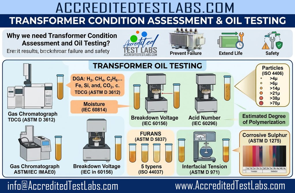
Transformer Condition Assessment and oil testing act as a diagnostic checkup for high-voltage assets. Transformer insulating oil cools the core and provides electrical insulation. Over time, thermal, electrical, and mechanical stresses degrade both the fluid and solid paper insulation. Regular testing detects internal faults early, prevents catastrophic failures, extends operational lifespan, and reduces unplanned downtime.

Transformer Condition Assessment TCA Oil Testing

Dissolved Gas Analysis (DGA) — ASTM D3612

Thermal and electrical stresses break down hydrocarbon oil molecules, generating characteristic dissolved gases.

  • $\text{H}_2$ (Hydrogen): Produced primarily by partial discharge (corona) and low-energy electrical arcing.
  • $\text{CH}_4$ (Methane): Indicates low-temperature thermal decomposition ($< 300^\circ\text{C}$) of the oil.
  • $\text{C}_2\text{H}_6$ (Ethane): Formed during local overheating at moderate temperatures ($300^\circ\text{C} – 500^\circ\text{C}$).
  • $\text{C}_2\text{H}_4$ (Ethylene): High-temperature thermal fault indicator ($> 700^\circ\text{C}$), suggesting severe local hot spots.
  • $\text{C}_2\text{H}_2$ (Acetylene): Critical indicator of high-energy electrical arcing or severe spark discharges ($> 700^\circ\text{C}$).
  • $\text{CO}$ (Carbon Monoxide): Indicates thermal degradation and overheating of the cellulose paper insulation.
  • $\text{CO}_2$ (Carbon Dioxide): Produced by normal aging or low-temperature thermal aging of paper insulation.
  • $\text{N}_2$ (Nitrogen) & $\text{O}_2$ (Oxygen): Measure air ingress, seal integrity, and oxidation potential inside the tank.
  • Total / TDCG / TDHHG / ETCG: Aggregated parameters measuring Total Dissolved Combustible Gas (TDCG), Heavy Hydrocarbon Gases (TDHHG), and Equivalent Total Combustible Gas (ETCG) to track overall fault severity and rate of gas generation.

Particle Counting — ISO 4406

Measures solid contaminant concentrations per 100 mL across specific size thresholds ($>4\mu, >6\mu, >14\mu, >21\mu, >38\mu, >70\mu$). High particle counts line up under electrical stress, bridging insulation gaps and triggering dielectric breakdown.

Physical & Chemical Oil Quality Parameters

  • Moisture Content (IEC 60814): Karl Fischer titration measuring water concentration (ppm). High moisture reduces dielectric strength and accelerates paper degradation.
  • Breakdown Voltage (IEC 60156): Measures the maximum voltage the oil can withstand before electrical breakdown occurs.
  • Acid Number (IEC 60296): Measures acidic oxidation byproducts. High acidity causes internal metal corrosion and sludge formation.
  • Interfacial Tension (ASTM D971): Measures surface tension between oil and water; lower values indicate soluble polar contaminants and advanced oil decay.
  • Color (ASTM D1500): Visual assessment scale ($0.5 – 8.0$) where darkening indicates contamination, oxidation, or severe overheating.
  • Power Factor @ $90^\circ\text{C}$ (IEC 60247): Measures dielectric power loss in the oil. Elevated values indicate moisture, soluble polar impurities, or sludge.
  • Flash Point (ASTM D93): Lowest temperature at which oil vapors ignite; lower values indicate volatile low-boiling hydrocarbons from fuel contamination or thermal cracking.
  • Kinematic Viscosity @ $40^\circ\text{C}$ (ASTM D445): Measures oil flow resistance; ensures proper heat dissipation and cooling performance.
  • Corrosive Sulphur (ASTM D1275): Detects reactive sulfur compounds (e.g., dibenzyl disulfide) that form conductive copper sulfide ($\text{Cu}_2\text{S}$) deposits on paper insulation, leading to short circuits.

Paper Degradation & Aging Indicators

  • Furans (ASTM D5837): Analyzes cellulose breakdown compounds dissolved in oil:
    • 5-Hydroxymethyl-2-furaldehyde (5H2F): Indicates early-stage paper degradation.
    • 2-Furaldehyde (2FAL): Main byproduct indicating overall paper aging and structural degradation.
    • 2-Acetylfuran (2ACF): Associated with localized thermal hotspots affecting paper.
    • 5-Methyl-2-furaldehyde (5M2F): Indicates severe local overheating of paper.
    • Furfuryl Alcohol (2FOL): Indicates moisture-driven hydrolytic paper breakdown.
  • Estimated Degree of Polymerization (DP) (IEC 61619): Calculates the average chain length of cellulose molecules (new paper $\text{DP} \approx 1000 – 1200$; end of life $\text{DP} \le 200$).
  • Induction Period @ $120^\circ\text{C}$ (IEC 61125 B): Evaluates the remaining oxidation stability and antioxidant inhibitor lifespan of the oil under accelerated thermal stress.

Want to learn more about full and advanced transformer oil tests? you may visit our dedicated page Transformer Oil Testing

Should you have any enquiries and looking for a competitive quote, feel free to contact us 24/7:

get a quote

Get a Quote Today
Instant response!
[email protected]
Middle East – Far East – Africa – Europe – America – Australia – Asia
contact today

Why Basic Diesel Testing is Necessary

Basic diesel testing is essential to ensure operational reliability, safety, regulatory compliance, and equipment protection. Unmonitored or off-spec fuel directly causes mechanical failures and costly downtime.

  • Engine Protection & Operational Reliability: Clean, properly specified fuel ensures efficient combustion and protects precision components. High water content causes injector corrosion and pump cavitation, while incorrect density or viscosity leads to incomplete combustion, power loss, and excessive carbon buildup.
  • Safety & Hazard Mitigation: Verifying parameters like flash point guarantees that fuel can be safely transported, stored, and handled. Contamination with volatile lighter fractions (like gasoline) significantly lowers the flash point, creating severe fire and explosion risks in fuel tanks and storage facilities.
  • Environmental & Regulatory Compliance: Environmental authorities enforce strict limits on total sulfur content (such as Ultra-Low Sulfur Diesel standards) to minimize sulfur dioxide ($\text{SO}_2$) emissions and harmful exhaust particulates. Testing verifies compliance before fuel hits the market, avoiding steep non-compliance fines.
  • Preventing Microbial Growth & System Clogging: Water accumulation in diesel storage tanks provides a breeding ground for bacteria and fungi (often called “diesel bug”). Testing detects moisture early, preventing biomass sludges from clogging filters and degrading fuel stability over time.
  • Commercial & Quality Assurance: Independent lab testing verifies that bulk fuel deliveries meet purchase contract specifications, preventing supplier disputes and ensuring the fuel has not been adulterated or contaminated during transit.
Why Basic Diesel Testing is necessary

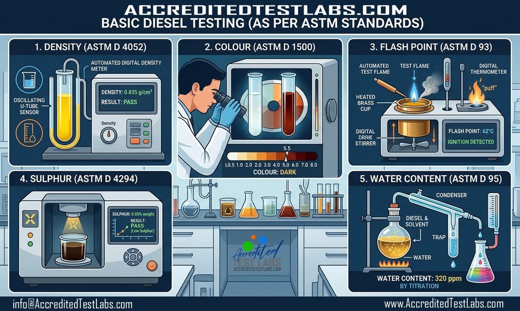
Basic Diesel Fuel Quality Tests

  • Density (ASTM D 4052): Measures the mass per unit volume of the fuel using a digital density meter with an oscillating U-tube. Density is critical for fuel injection systems, as it affects the mass of fuel injected into the combustion chamber, influencing power output, fuel economy, and engine emissions.
  • Colour (ASTM D 1500): Determines the color scale value (ranging from 0.5 to 8.0) using a standardized color comparator. This serves as a quick quality control check; sudden darkening or off-spec color indicates potential contamination, age degradation, or mixing with heavier fuels.
  • Flash Point (ASTM D 93): Determines the lowest temperature at which diesel vaporizes and forms an ignitable mixture with air using a Pensky-Martens closed-cup tester. It is essential for handling and storage safety regulations to prevent accidental fire hazards and flags contamination by more volatile fuels like gasoline.
  • Sulphur Content (ASTM D 4294): Measures total sulfur concentration using Energy-Dispersive X-ray Fluorescence (EDXRF) spectrometry. Controlling sulfur is vital to comply with environmental emission standards (e.g., Ultra-Low Sulfur Diesel specifications) and to prevent exhaust system corrosion and particulate filter damage.
  • Water Content (ASTM D 95): Determines the amount of free and emulsified water in the fuel via distillation with an immiscible solvent. Excess water leads to microbial growth, filter plugging, corrosion of fuel lines, and severe damage to high-pressure fuel injectors.

Want to learn more about full and advanced diesel tests? you may visit our dedicated page Diesel Testing

Should you have any enquiries and looking for a competitive quote, feel free to contact us 24/7:

get a quote

Get a Quote Today
Instant response!
[email protected]
Middle East – Far East – Africa – Europe – America – Australia – Asia
contact today

What is OCM and Why It is Required for Lubricants

Why OCM Analysis is Necessary to Avoid Engine Failures

  • Early Failure Detection: Spectrometric wear metal analysis spots microscopic component degradation long before physical symptoms (such as overheating, noise, or pressure drops) manifest.
  • Prevention of Corrosion: Monitoring TBN/TAN ensures the oil retains sufficient reserve alkalinity to prevent acidic combustion byproducts from etching bearings, cylinder walls, and liners.
  • Contamination Control: Fast identification of coolant leaks (water content), blown fuel injectors (fuel dilution affecting flash point and viscosity), or failed air filters (silicon) allows corrective action before severe mechanical failure occurs.
  • Lubrication Maintenance: Verifying kinematic viscosity ensures moving parts maintain adequate film thickness, preventing direct metal-to-metal contact, scuffing, and thermal seizure.
  • Condition-Based Maintenance: OCM moves operations away from fixed calendar-based oil changes to condition-driven drain intervals, extending component lifespan while avoiding catastrophic secondary engine damage.
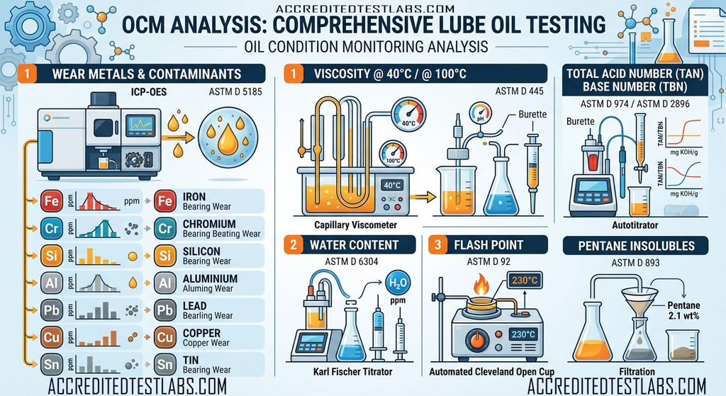
Lube Oil Testing OCM Analysis

1. Wear Metals & Contaminants (ASTM D 5185)

  • Method: Analyzed using ICP-OES (Inductively Coupled Plasma Optical Emission Spectroscopy).
  • Parameters Tested: Iron (Fe), Chromium (Cr), Silicon (Si), Aluminium (Al), Lead (Pb), Copper (Cu), and Tin (Sn) measured in parts per million (ppm).
  • Function: Identifies microscopic metal particles and external abrasives in the oil. Elevated concentrations point to specific wearing engine components (e.g., Fe/Cr from cylinder liners and rings; Pb/Cu/Sn from bearings; Si from external dirt ingress).

2. Viscosity @ 40°C / Viscosity @ 100°C (ASTM D 445)

  • Method: Measured using glass capillary viscometers in a temperature-controlled bath.
  • Function: Viscosity determines the oil’s ability to maintain a protective lubrication film. High viscosity indicates oxidation, soot accumulation, or sludge build-up; low viscosity flags fuel dilution or additive shear degradation.

3. Total Acid Number (TAN) & Base Number (TBN) (ASTM D 974 / ASTM D 2896)

  • Method: Measured via potentiometric or color-indicator titrations using automated titrators.
  • Function: TBN tracks the remaining alkaline reserve meant to neutralize corrosive combustion acids. TAN measures total acidic accumulation. A dropping TBN paired with a rising TAN signals oil degradation and risk of internal chemical corrosion.

4. Water Content (ASTM D 6304)

  • Method: Determined via Karl Fischer Coulometric Titration.
  • Function: Detects free, emulsified, or dissolved water (in ppm). Moisture degrades oil additives, causes rust, promotes cavitation, and disrupts oil film strength.

5. Flash Point (ASTM D 92)

  • Method: Tested using a Cleveland Open Cup apparatus by heating the sample until vapors ignite.
  • Function: A significant drop in flash point indicates volatile fuel contamination (fuel dilution), which lowers lubrication capability and poses a combustion risk.

6. Pentane Insolubles (ASTM D 893)

  • Method: Evaluated through solvent mixing, centrifugation, and membrane filtration.
  • Function: Measures insoluble solid contaminants like soot, resin, oxidized organic matter, and external dirt, identifying filtration issues or combustion blow-by.

Want to learn more about extended tests including FTIR, Oxidation, Nitration, Sulfation, Soot? you may visit our dedicated page Lube Oil Testing

Should you have any enquiries and looking for a competitive quote, feel free to contact us 24/7:

get a quote

Get a Quote Today
Instant response!
[email protected]
Middle East – Far East – Africa – Europe – America – Australia – Asia
contact today

What is UREA SCR System on Vessel

Understanding What is UREA of SCR System on Vessel

On a marine vessel, the UREA onboard SCR system is an exhaust-gas treatment system used to reduce NOx (nitrogen oxides) from the main engine or auxiliary engines. SCR stands for Selective Catalytic Reduction.

Basic principle

The system injects a urea solution (usually 40% urea / 60% water for marine applications, depending on the manufacturer) into the engine exhaust. The urea decomposes into ammonia (NH₃), which reacts with NOx over a catalyst.

NOx + NH₃ → N₂ + H₂O

So, the harmful NOx is converted mainly into nitrogen and water.

Typical onboard arrangement

A marine SCR system can be thought of as:

Engine → Exhaust pipe → Urea injection → Mixing section → SCR catalyst → Clean exhaust → Funnel

The major equipment normally includes:

  • Urea storage tank – stores the urea solution.
  • Urea transfer/pumping system – supplies urea to the SCR unit.
  • Dosing/injection unit – accurately injects the required amount of urea.
  • Mixing unit – ensures good mixing of urea-derived ammonia with the exhaust gas.
  • SCR reactor/catalyst – where the NOx reduction reaction occurs.
  • NOx sensors – measure NOx before/after treatment.
  • Exhaust temperature sensors – SCR requires an appropriate exhaust temperature.
  • Control system/PLC – controls dosing and monitors the system.
  • Bypass valve/damper – depending on the installation, allows exhaust to bypass the SCR under certain conditions.

Why is it installed on ships?

The main purpose is to comply with IMO MARPOL Annex VI NOx emission requirements, particularly IMO Tier III requirements in applicable NOx Emission Control Areas (NECAs).

For example, when a vessel enters a NOx-controlled area, the SCR may be activated to achieve the required NOx reduction. The exact operating arrangement depends on the engine and SCR manufacturer.

What happens if urea runs out?

The consequences depend on the vessel’s system and control philosophy. Typically, the SCR system will generate alarms such as:

  • Low urea level
  • Urea pump failure
  • Low urea pressure
  • High/low exhaust temperature
  • NOx sensor fault
  • SCR catalyst differential-pressure/high pressure alarm
  • Poor NOx conversion

If the vessel is required to meet Tier III limits in the applicable operating area, loss of SCR operation can become a compliance issue, so the crew normally needs to follow the vessel’s approved operating/emergency procedure.

Important distinction: Urea vs. fuel

The urea system is separate from the fuel system.

Fuel → engine combustion → exhaust → SCR + urea → reduced NOx

The urea is not burned in the engine. It is injected into the exhaust after combustion.

What is Vegetable Acid Oil, its uses, and Testing

Vegetable Acid Oil

Vegetable acid oil (VAO) is a secondary product generated during the refining of vegetable oils. It can result from the processing of crude oils such as soybean, palm, sunflower, canola, and other plant-based oils.

VAO consists predominantly of free fatty acids (FFAs), together with varying amounts of neutral oil, moisture, and other minor constituents.

Production Process

During the refining of crude vegetable oil, free fatty acids are commonly removed through alkali neutralization, producing a by-product known as soapstock. This soapstock is subsequently treated with an acid, such as sulfuric acid, to separate the fatty acids from the soap. The resulting fatty, acidic material is referred to as vegetable acid oil.

Main Characteristics

  • Contains a relatively high concentration of free fatty acids, commonly ranging from approximately 50% to 90%, depending on the oil source and manufacturing process.
  • Generally has a darker appearance than refined vegetable oils.
  • Typically possesses a noticeable fatty or oily odor.
  • It is generally not intended for direct human consumption.
  • Its chemical and physical properties can differ significantly according to the type of vegetable oil from which it is produced.

Applications

Vegetable acid oil has several commercial and industrial applications, including:

  • Animal feed: Used as a source of dietary fat and energy when it meets applicable feed-quality requirements.
  • Soap and detergent production: Utilized as a feedstock for manufacturing soaps and related products.
  • Biodiesel production: Can serve as a low-cost feedstock for producing biodiesel.
  • Oleochemical manufacturing: Used in the production of fatty acids and other oleochemical products.
  • Other industrial applications: Its high fatty-acid content makes it useful in various chemical and manufacturing processes.

Recommended VAO testing parameters and methods

ParameterTypical reporting unitCommon test methodPurpose
Free Fatty Acids (FFA)% as oleic acidAOCS Ca 5a-40Measures the level of free fatty acids; one of the most important VAO parameters
Acid Value (AV)mg KOH/gTitrimetric method; can be calculated from FFAIndicates total acidity of the oil
Moisture & Volatile Matter%AOCS Ca 2b-38Determines water and volatile components
Insoluble Impurities%AOCS Ca 3a-46Measures dirt, suspended solids and other insoluble material
MIU%Moisture + Insoluble Impurities + Unsaponifiable matterImportant commercial quality parameter, particularly for feed/industrial trade
Unsaponifiable Matter%AOCS Ca 6a-40Determines non-saponifiable components
Iodine Value (IV)g I₂/100 gAOCS Cd 1d-92Indicates degree of unsaturation
Peroxide Value (PV)meq O₂/kgAOCS Cd 8b-90Measures primary oxidation products
Saponification Valuemg KOH/gAOCS Cd 3-25Characterizes fatty-acid chain-length distribution
ColorLovibond / AOCS colorAOCS Cc 13b-45 / Cc 13j-97Determines visual color quality
Fatty Acid Composition (FAME/GC)% of individual FAAOCS Ce 1i-07 or applicable ISO methodIdentifies and quantifies individual fatty acids
Neutral Oil / Triglycerides%AOCS Ca 9f-57 or suitable chromatographic methodDetermines the amount of neutral oil remaining in VAO
Phosphorusmg/kgAppropriate ICP/AAS or validated oil methodUseful for assessing phospholipid/processing residues
Soapppm or %AOCS soap method, where applicableDetects residual soap from refining
Trace metalsmg/kgICP-OES/ICP-MSImportant for feed and biodiesel applications
Tocopherols/Tocotrienolsmg/kgHPLCOptional; useful for characterization and oxidation assessment

AOCS lists FFA, iodine value, peroxide value, moisture, fatty-acid composition and p-anisidine value among established analytical determinations for vegetable oils, with methods including Ca 5a-40, Cd 1d-92, Cd 8b-90, Ca 2b-38 and Ce 1i-07. AOCS also lists insoluble impurities and unsaponifiable matter methods for fats and oils.

1. Free Fatty Acids (FFA)

This is usually the most important parameter for VAO.

Method: AOCS Ca 5a-40
Principle: The sample is dissolved in an appropriate alcohol/solvent mixture and titrated with standardized alkali using an indicator. The result is generally expressed as % FFA calculated as oleic acid.

For example, if a specification says:

FFA = 70%

it means approximately 70% of the material is present as free fatty acids on the specified calculation basis.

AOCS specifically lists Ca 5a-40 for FFA determination in vegetable oils and fats.

2. Acid Value

Acid value is closely related to FFA and is expressed as mg KOH required to neutralize the acidic components in 1 g of sample.

For an oil where FFA is calculated as oleic acid:

Acid Value ≈ FFA (%) × 1.99

So, for example, 70% FFA corresponds approximately to an acid value of 139 mg KOH/g.

However, for commercial specifications, you should report FFA and acid value separately rather than assuming they are interchangeable.

3. Moisture

Method: AOCS Ca 2b-38 is one established method used for moisture in fats and oils.

High moisture can cause:

  • Hydrolysis
  • Increased corrosion
  • Storage problems
  • Biodiesel-processing difficulties
  • Reduced feed quality

For VAO, Karl Fischer titration may also be appropriate where a more specific water determination is required.

4. Insoluble Impurities

Method: AOCS Ca 3a-46 is listed for insoluble impurities in fats and oils.

This determines material that does not dissolve in the specified solvent, such as:

  • Dirt
  • Sediment
  • Processing residues
  • Foreign particulate matter

5. Unsaponifiable Matter

Method: AOCS Ca 6a-40.

This fraction includes substances that do not form soaps during saponification, such as certain sterols, hydrocarbons and related compounds.

It is particularly useful when calculating MIU (Moisture, Insoluble impurities and Unsaponifiable matter).

6. Iodine Value

Method: AOCS Cd 1d-92.

Iodine value provides an indication of the degree of unsaturation of the fatty acids.

Generally:

  • Higher IV → greater unsaturation
  • Lower IV → greater saturation

This is particularly important if the VAO is intended for biodiesel production, because fatty-acid unsaturation affects oxidation stability and other fuel properties.

7. Peroxide Value

Method: AOCS Cd 8b-90.

PV measures primary oxidation products, principally hydroperoxides.

A high PV generally indicates that the material has undergone greater oxidative deterioration. For stored VAO, PV should therefore be monitored along with other oxidation indicators.

8. Fatty Acid Profile

Method: Gas chromatography of fatty-acid methyl esters (FAME), with an appropriate AOCS/ISO method such as AOCS Ce 1i-07.

A typical report may include:

  • C16:0 — Palmitic acid
  • C18:0 — Stearic acid
  • C18:1 — Oleic acid
  • C18:2 — Linoleic acid
  • C18:3 — Linolenic acid

The profile is especially useful for identifying the source of the VAO—for example, palm, soybean, sunflower, rapeseed/canola, etc.

9. Neutral Oil

Neutral oil represents the fraction of glycerides that remains in the acid oil in addition to the free fatty acids.

AOCS lists Ca 9f-57 for neutral oil determination in soybean oil proficiency testing.

This parameter can be commercially important because two VAO samples with the same FFA may have substantially different amounts of neutral oil.


Practical VAO specification panel

If you are testing vegetable acid oil for commercial purchasing/selling, I would recommend at minimum:

  1. FFA (%)
  2. Moisture (%)
  3. Insoluble impurities (%)
  4. Unsaponifiable matter (%)
  5. MIU (%)
  6. Iodine value
  7. Peroxide value
  8. Saponification value
  9. Color
  10. Neutral oil (%)
  11. Fatty acid composition by GC
  12. Phosphorus
  13. Soap
  14. Density/specific gravity
  15. Trace metals, if required for the intended application

For animal-feed VAO, additional attention should be given to oxidation status, unsaponifiable matter, fatty-acid profile, contaminants and the suitability of the analytical method for acid oils. Research specifically examining acid oils used in animal feeding notes that conventional official methods may need modification to obtain reliable results with these materials.

If you tell me whether your VAO is palm oil acid oil, soybean acid oil, sunflower acid oil, or mixed vegetable acid oil, I can also give you a complete laboratory specification table with parameter, acceptable range, unit, AOCS/ISO method, apparatus, chemicals, calculation formula, and sample COA format.

Should you have any enquiries and looking for a competitive quote, feel free to contact us 24/7:

get a quote

Get a Quote Today
Instant response!
[email protected]
Middle East – Far East – Sub-continent – Africa – Europe – America – Australia – Asia

contact today

Effects of Poor Sampling or handling on Analysis Results

Sampling must have to be taken into account significantly to produce reliable results. No matter how modern techniques we are following in analysis or even if we are using the latest test equipment, all goes wasted if sampling is compromised.

Here is a small light thrown over aspects and results a poor sampling or sample handling can yield.

  • Poor sampling can lead to non-representative oil samples, giving results that do not reflect the actual condition of the oil.
  • Contamination during sampling can falsely increase parameters such as moisture, particles, metals, or acidity.
  • Improper sampling location may miss localized contamination or degradation.
  • Insufficient sample mixing can cause separation of contaminants and produce inconsistent results.
  • Exposure to air or moisture during sampling can alter oxidation, moisture, and other chemical test results.
  • Dirty or unsuitable sampling containers can introduce external contaminants and affect laboratory analysis.
  • Incorrect sample quantity may be insufficient for all required tests or affect test accuracy.
  • Improper storage or delayed testing can change the oil’s properties before analysis.
  • Incorrect labeling or identification can result in analysis being performed on the wrong sample or incorrect interpretation of results.
  • Overall effect: Bad sampling can produce false, misleading, or unreliable analytical results, leading to incorrect conclusions about oil quality and equipment condition.

We at AccreditedTestLabs.com, always ensure proper sampling and sample handling as per SOPs prescribed by national and International standards. Learn more about our sampling services, types, capability, and worldwide coverage here : – Professional Sampling Services

Sampling Services for oil, gas, food, water, material.

What is MGO and why does it require Testing?

MGO (Marine Gasoil) is a high-quality, low-viscosity marine fuel used in ships. It is a distillate fuel, similar to automotive diesel, but formulated to meet marine engine requirements. Compared with heavy fuel oil (HFO), MGO is cleaner-burning, contains fewer impurities, and usually has much lower sulfur content.

What is MGO used for?

Marine gasoil is commonly used in:

  • Main and auxiliary marine diesel engines.
  • Ships operating in areas with strict emission regulations.
  • Port operations, where cleaner fuels are often required.
  • Smaller vessels, ferries, offshore vessels, and emergency generators.

Why is MGO testing required?

Testing ensures the fuel is safe, compliant, and suitable for the engine. Poor-quality MGO can lead to engine damage, higher maintenance costs, and non-compliance with environmental regulations.

Key reasons for testing include:

  1. Verify fuel quality
    • Confirms the fuel meets specifications such as the ISO 8217 marine fuel standard.
    • Ensures the supplied fuel matches what was purchased.
  2. Protect engine components
    • Detects contaminants like water, sediments, or abrasive particles that can damage fuel pumps, injectors, and filters.
  3. Check sulfur content
    • Verifies compliance with international and local emission limits.
    • Prevents penalties for using non-compliant fuel.
  4. Prevent operational problems
    • Identifies issues that could cause poor combustion, excessive smoke, injector fouling, or engine knocking.
  5. Detect contamination
    • Finds contamination from other fuels, lubricating oil, seawater, or chemicals that may have occurred during storage or bunkering.
  6. Support warranty and dispute resolution
    • Independent test reports can help resolve fuel quality disputes between ship operators and fuel suppliers.

Common MGO tests

TestPurpose
DensityDetermines fuel quality and energy content.
Kinematic viscosityEnsures proper fuel flow and injector performance.
Sulfur contentChecks environmental compliance.
Flash pointConfirms safe handling and storage.
Water contentDetects free or dissolved water that can cause corrosion and poor combustion.
Sediment/particulatesIdentifies solid contaminants that can clog filters and wear components.
Cold Filter Plugging Point (CFPP) or Cloud PointEvaluates low-temperature operability.
Cetane IndexIndicates ignition quality.
Ash contentMeasures inorganic residues that can form deposits.
LubricityEnsures adequate protection for fuel injection equipment.
Acid numberDetects fuel degradation and corrosive compounds.
Microbial contaminationChecks for bacterial or fungal growth in storage tanks.

Typical testing sequence

  1. Collect a representative fuel sample during bunkering or from the storage tank.
  2. Send the sample to an accredited laboratory.
  3. Compare the results with the applicable specification (such as ISO 8217) and the supplier’s fuel documentation.
  4. Take corrective action if the fuel fails any critical parameter before using it extensively.

Summary

MGO testing is essential because it:

  • Ensures fuel complies with standards.
  • Protects marine engines from wear and failures.
  • Confirms compliance with environmental regulations.
  • Improves fuel efficiency and engine reliability.
  • Helps avoid costly repairs, downtime, and fuel quality disputes.

In practice, MGO testing is a routine part of fuel quality assurance for commercial shipping and is especially important after bunkering, before long voyages, or whenever fuel contamination is suspected.

Should you have any testing requisites and looking for a competitive quote, feel free to contact us 24/7:

get a quote

Get a Quote Today
Instant response!
[email protected]
Middle East – Far East – Africa – Europe – America – Australia – Asia

contact today

For more information about full range of Oil and Gas Testing Services please visit our page Oil and Gas Testing